
- #Battery isolator switch wiring diagram how to#
- #Battery isolator switch wiring diagram professional#
My installation obviously has separate wires from starter and alternator.


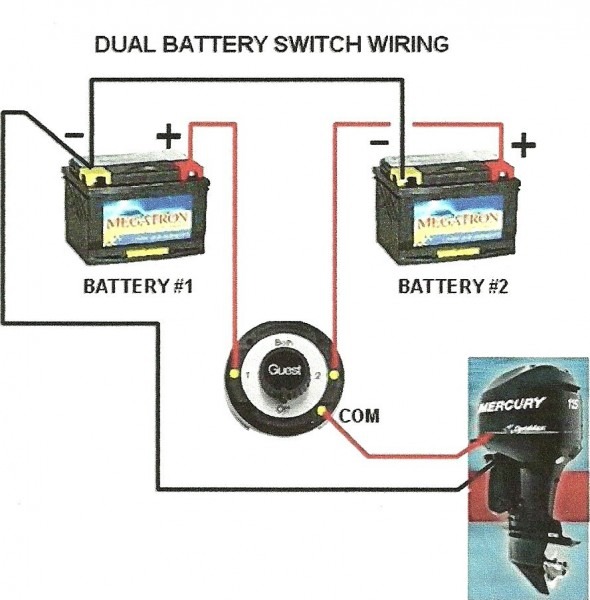
On the other hand the wiring diagram for the Yanmar 2GM20F engine shows the alternator output joined to starter motor and then going to the battery via an isolator switch, which thus controls both the load and charging circuits. For instance, in case a module will be powered up also it sends out a new signal of 50 percent the voltage in addition to the technician will not know. Effectively read a wiring diagram, one offers to learn how typically the components inside the program operate. On the face of it I can't see anything wrong with this arrangement: the alternator diodes should prevent any current leakage from the batteries when the boat is not in use and the diodes can't be blown due to having an open circuit on the alternator output. Multi Battery Isolator Wiring Diagram from. Therefore the batteries are not truly isolated when the switches are open because their charging circuits are still connected. The alternator output is permanently connected to the batteries via a diode splitter. the starter motor and domestic loads respectively. The engine and domestic batteries each have their own isolator switch, but these only control the load circuits i.e.
#Battery isolator switch wiring diagram how to#
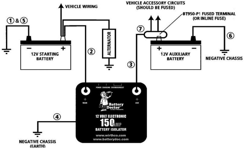
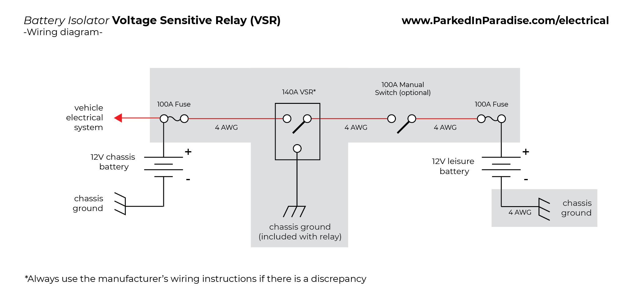
For more information on battery isolator switches and how to properly install them, please refer to the manufacturer’s instructions and any wiring diagrams provided.I've been investigating the wiring of my new (to me) boat. It can help ensure that the vehicle’s electrical system remains safe and reliable. Having a wiring diagram for a battery isolator switch is indispensable for anyone who owns a vehicle that relies on multiple batteries for power. Additionally, it’s important to inspect the battery isolator switch regularly to ensure that it is functioning correctly.
#Battery isolator switch wiring diagram professional#
If you are unsure, it’s best to contact a professional for assistance with the installation. It’s important to note that all wiring diagrams should be followed exactly, as any mistakes can cause serious damage to the electrical system. It will show how the wires need to be connected and what needs to be done when the switch is activated. This diagram should provide detailed information on the type of isolation switch being used and its components. When installing a battery isolator switch, it’s important to follow all instructions carefully and use the right wiring diagram. It also prevents overcharging of the batteries, reducing the risk of damage or fire. This helps keep the vehicle operational in case of a battery failure. It allows for the isolated battery to be disconnected from the rest of the main battery bank so that it can be charged or replaced without having to turn off power to the other batteries. A battery isolator switch is typically used in vehicles that use multiple batteries for power, such as in RV’s, boats and heavy-duty machinery. Without a wiring diagram, it can be difficult to properly install and use a battery isolator switch. The switch isolates the battery from the rest of the vehicle's systems and prevents unnecessary draining of the battery's charge. A wiring diagram for a battery isolator switch is an essential part of any vehicle electrical system.


 0 kommentar(er)
